Understanding the protocol
The first job was taking a look at the provided information. The added file boxy.txt is not particularly helpful in this regard (looked quite Chineese to me, my brother who happens to speak Chinese insisted it isn’t). So I directly moved on to the examples provided and luckily they were extremely helpful. The first image(0x00.bin) consisted of only 8 bytes and only painted a white square. The second example was a little harder to understand at first, because it comes with only one binary and multiple output files, that show squares in different colors.
01 FF 02 FF 03 00 FF 00 03 01 FF 00 03 02 FF 00 03 03 FF 00 03 04 FF 00 03 05 FF 00 03 06 FF 00 03 07 FF 00
The first thing to notice is the fact that the first bytes are equal to (0x00.bin) and afterwards the sequence 03 0X FF 00 repeats 7 times, which corresponds with the number of available output pictures. Based on this we can start to make some assumptions:
- The byte sequence
00 FFseems to be some kind of terminator between different commands. - The byte sequence
03 0Xseems to indicate a color change with possible values for X between 00 and 07. - The bytes seem come in pairs, with the first byte as a key and thnue second byte being the value.
The next example (0x02.bin) shows us how multiple different rectangles are drawn:
01 80 02 80 03 00 FF 00 04 80 05 80 FF 00 03 01 04 00 05 80 FF 00 04 80 05 00 FF 00
We notice that the values for 01 and 02 have halved from 0xFF to 0x80. And we see two new keys, 0x04 and 0x05, which change between the different rectangles. The key 03 only changes once (from white to black). Based on that observation we can draw the following conclusions:
- The keys 01 and 02 determine the size of the rectangle.
- The key 03 determines the color of the rectangle
- The keys 04 and 05 determine the position of the rectangle
- Each occurance of
FF 00indicates that one rectangle is finished and a new one begins. - Every key that is not set, retains the value from the previous rectangle.
The final example now draws 4 differently colored rectangles on a white square:
01 FF 02 FF 03 00 FF 00 01 08 02 10 04 58 05 58 03 02 07 40 FF 00 03 03 09 40 FF 00 03 04 06 40 FF 00 03 05 08 40 FF 00
We get four new additional keys, that can be used to shift a rectangle away from the position specified by the values in 04 and 05.
- Key 06 decreases the value of 04 by its value.
- Key 07 increases the value of 04 by its value.
- Key 08 decreases the value of 05 by its value.
- Key 09 increases the value of 05 by its value.
And with that information the protocol has been reversed…
Getting the flag
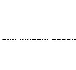
With this information you should be able to implement a program which prints the image described in the reverseme binary. I personally choose Java Swing (but that is only because of a traumatic university assignment that left me far too familiar with this technology, it is certainly not a recommendation). As soon as you get that working you have an image which contains a sequence of dots and dashes, which should immediately make you think of Morse Code.

Figure 1 - Example for how reversed image should look like
If we decode every 5 character sequence correctly the morse code transforms into a sequence of decimal numbers. If you through these numbers into a decimal to ascii converter you receive the flag.